This example demonstrates how to attach multiple L2VNIs to the same L3VNI so that the L2 overlays become routable between each other, while still reaching the broader L3 domain.
Overview #
The Layer 2 Integration example connects pods that share a single L2 subnet: traffic between them is bridged, never routed.
This example goes one step further. Two separate L2VNIs — each with its own subnet and
anycast gateway — reference the same L3VNI via routingDomain. Because both L2
segments live in the same VRF, OpenPERouter routes traffic between them locally, without
leaving the overlay. This is the classic symmetric IRB (Integrated Routing and
Bridging) topology: every L2VNI is a bridge domain, and the shared L3VNI is the VRF that
stitches them together.
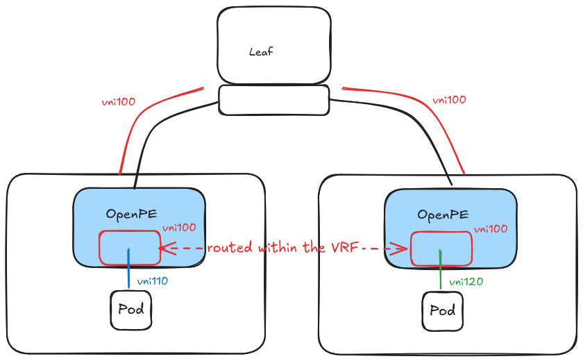
Both pods sit on different L2VNIs (bridge domains), yet because those L2VNIs share the
red VRF, traffic between them is routed locally in the overlay — it never leaves for the
external fabric and it is not NATed.
Example Setup #
The full example can be found in the project repository and can be deployed by running:
make docker-build demo-l2vnis-with-same-l3vni
The example configures one L3VNI (red) and two L2VNIs (blue and green), both
belonging to the red routing domain. A pod is placed on each subnet, on two separate
nodes, and connected through the overlay.
How Traffic Flows #
- Same subnet (L2): pods on the same L2VNI reach each other by bridging, encapsulated in that L2VNI (see the Layer 2 Integration example).
- Across subnets (routed): when a pod on the
bluesubnet reaches a pod on thegreensubnet, the packet hits its anycast gateway on the localbr-pe-110interface, is routed inside theredVRF tobr-pe-120, and delivered over thegreenL2VNI. - To the external L3 domain: as with a single L2VNI, traffic to a host on the
rednetwork is routed in theredVRF and follows the EVPN Type 5 routes.
Configuration #
OpenPERouter Configuration #
One L3VNI corresponding to the routing domain, and two L2VNIs each referencing it via
routingDomain. Each L2VNI carries its own subnet through gatewayIPs:
apiVersion: network.openperouter.io/v1alpha1
kind: L3VNI
metadata:
  name: red
  namespace: openperouter-system
spec:
  vrf: red
  vni: 100
  hostSession:
    asn: 64514
    hostASN: 64515
    localCIDRs:
      - 192.169.10.0/24
---
apiVersion: network.openperouter.io/v1alpha1
kind: L2VNI
metadata:
  name: finance-net
  namespace: openperouter-system
spec:
  vni: 110
  routingDomain:
    type: L3VNI
    l3vni:
      name: red
  hostMaster:
    type: LinuxBridge
    linuxBridge:
      lifecycle: Managed
  gatewayIPs: ["192.170.1.1/24"]
---
apiVersion: network.openperouter.io/v1alpha1
kind: L2VNI
metadata:
  name: hr-net
  namespace: openperouter-system
spec:
  vni: 120
  routingDomain:
    type: L3VNI
    l3vni:
      name: red
  hostMaster:
    type: LinuxBridge
    linuxBridge:
      lifecycle: Managed
  gatewayIPs: ["192.170.2.1/24"]
Configuration Notes:
- Shared
routingDomain: both L2VNIs point at the same L3VNI (red), so both live in theredVRF. This is what makes their subnets routable between each other. - Distinct
gatewayIPs: each L2VNI owns a different subnet and a different anycast gateway. The subnets must not overlap — OpenPERouter rejects overlapping subnets within the same VRF. - One L3VNI per VRF: a VRF may back only one L3VNI, but any number of L2VNIs may reference that L3VNI.
Network Attachment Definitions #
One macvlan attachment per L2VNI, each mastered by that L2VNI’s local bridge
(br-hs-<vni>) and pointing at the matching anycast gateway:
apiVersion: "k8s.cni.cncf.io/v1"
kind: NetworkAttachmentDefinition
metadata:
  name: macvlan-blue
spec:
  config: '{
      "cniVersion": "0.3.0",
      "type": "macvlan",
      "master": "br-hs-110",
      "mode": "bridge",
      "ipam": {
         "type": "static",
         "routes": [ { "dst": "0.0.0.0/0", "gw": "192.170.1.1" } ]
      }
    }'
---
apiVersion: "k8s.cni.cncf.io/v1"
kind: NetworkAttachmentDefinition
metadata:
  name: macvlan-green
spec:
  config: '{
      "cniVersion": "0.3.0",
      "type": "macvlan",
      "master": "br-hs-120",
      "mode": "bridge",
      "ipam": {
         "type": "static",
         "routes": [ { "dst": "0.0.0.0/0", "gw": "192.170.2.1" } ]
      }
    }'
Workload Configuration #
Two pods, one per subnet, scheduled on different nodes:
apiVersion: v1
kind: Pod
metadata:
  name: blue
  annotations:
    k8s.v1.cni.cncf.io/networks: '[{
      "name": "macvlan-blue",
      "namespace": "default",
      "ips": ["192.170.1.3/24"]
      }]'
spec:
  nodeName: pe-kind-worker
  containers:
    - name: agnhost
      image: k8s.gcr.io/e2e-test-images/agnhost:2.45
      command: ["/bin/sh", "-c", "ip r del default dev eth0 && /agnhost netexec --http-port=8090"]
      securityContext:
        capabilities:
          add: ["NET_ADMIN"]
---
apiVersion: v1
kind: Pod
metadata:
  name: green
  annotations:
    k8s.v1.cni.cncf.io/networks: '[{
      "name": "macvlan-green",
      "namespace": "default",
      "ips": ["192.170.2.3/24"]
      }]'
spec:
  nodeName: pe-kind-worker2
  containers:
    - name: agnhost
      image: k8s.gcr.io/e2e-test-images/agnhost:2.45
      command: ["/bin/sh", "-c", "ip r del default dev eth0 && /agnhost netexec --http-port=8090"]
      securityContext:
        capabilities:
          add: ["NET_ADMIN"]
Note: We remove the default gateway on
eth0so that the secondary interface default gateway (the anycast gateway) is the only active one, forcing cross-subnet traffic through OpenPERouter.
Validation #
Routing Between the Two L2 Overlays #
The blue pod (192.170.1.3) is on a different subnet than the green pod
(192.170.2.3). Reaching one from the other requires routing in the red VRF:
kubectl exec -it blue -- curl 192.170.2.3:8090/clientip
Expected output (the source IP is preserved, confirming the traffic was routed, not NATed):
192.170.1.3:44564
The reverse direction works the same way:
kubectl exec -it green -- curl 192.170.1.3:8090/clientip
You can confirm the packet is routed (its TTL is decremented and the destination MAC
changes at the anycast gateway) by capturing traffic in the OpenPERouter namespace on the
blue pod’s node. The packet enters on the blue L2VNI bridge (br-pe-110), is handed
to the red VRF, and leaves encapsulated in the green L2VNI (vni 120):
pe-110    P   IP 192.170.1.3.44564 > 192.170.2.3.8090: Flags [S], seq 0, length 0
br-pe-110 In  IP 192.170.1.3.44564 > 192.170.2.3.8090: Flags [S], seq 0, length 0
br-pe-120 Out IP 192.170.1.3.44564 > 192.170.2.3.8090: Flags [S], seq 0, length 0
vni120    Out IP 192.170.1.3.44564 > 192.170.2.3.8090: Flags [S], seq 0, length 0
toswitch  Out IP 100.65.0.0.39370 > 100.65.0.1.4789: VXLAN, flags [I] (0x08), vni 120
              IP 192.170.1.3.44564 > 192.170.2.3.8090: Flags [S], seq 0, length 0
Contrast this with the single-subnet Layer 2 Integration example, where the packet is bridged out of the same VNI it came in on and no routing takes place.
Reaching the External L3 Domain #
Because both L2VNIs share the red VRF, either pod can still reach a host on the external
red network (with 192.168.20.2 being a host on that network):
kubectl exec -it green -- curl 192.168.20.2:8090/clientip
The pod is able to reach the L3 network and its IP is preserved, exactly as in the single-L2VNI case.
Fabric requirement: for this leg to work, the fabric leaf that owns the external
redsubnet must originate an EVPN Type 5 route for it. In the development environment this is handled automatically:make demo-l2vnis-with-same-l3vnideploys the fabric withDEMO_MODE=true, which enablesredistribute connectedin the leaves’redVRF (seeclab/scripts/02-leaf-configs.sh). Without it, inter-L2VNI routing between the pods still works, but the external L3 leg has no route back and fails.
DEMO_MODEis applied only when the fabric is first created —make deployskips reconfiguration if the cluster already exists. If you brought the environment up without it, tear it down (make clean) and redeploy viamake demo-l2vnis-with-same-l3vni.