OpenPERouter implements EVPN (Ethernet VPN) over VXLAN to provide scalable overlay networking. EVPN serves as the control plane protocol that enables the distribution of MAC and IP reachability information across the network fabric, while VXLAN provides the data plane encapsulation for overlay traffic.
The solution supports two main overlay types:
L3VNI (Layer 3 Virtual Network Identifier): Creates routed overlay networks where IP connectivity is extended across the fabric. Each L3VNI corresponds to a VRF (Virtual Routing and Forwarding) instance that maintains separate routing tables and enables IP-based communication between endpoints.
L2VNI (Layer 2 Virtual Network Identifier): Creates bridged overlay networks where Layer 2 connectivity is extended across the fabric. L2VNIs enable MAC learning and forwarding, allowing endpoints to communicate at the Ethernet layer as if they were on the same physical LAN segment.
Both overlay types can coexist and interoperate, enabling flexible network designs that combine routed and bridged domains as needed.
Underlay Connectivity #
VTEP IP Assignment #
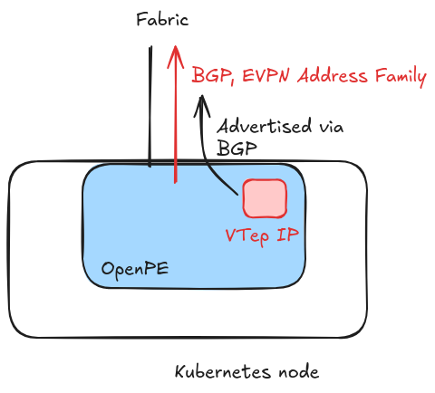
Each OpenPERouter instance requires a unique IP address to use as the VXLan VTEP (Virtual Tunnel End Point). This address must be reachable from every other VTEP in the network.
OpenPERouter can either assign a VTEP IP to its loopback interface or use the IP of an existing interface that is already reachable through the fabric underlay. See the EVPN configuration page for details on how to configure each mode.
OpenPERouter establishes a BGP session with the fabric with the VPN address family enabled, allowing the exchange of EVPN routes required for overlay connectivity.
Overlay Networks (VNIs) #
Virtual Network Identifiers #
OpenPERouter supports the creation of multiple VNIs (Virtual Network Identifiers), each corresponding to a separate EVPN tunnel. This enables multi-tenancy and network segmentation.
OpenPERouter supports the creation of L3 VNIs, allowing the extension of a routed domain via an EVPN overlay:

It supports the creation of L2 VNIs, where the veth is directly connected to a layer 2 domain

And it also supports a mixed scenario, where an L2 domain also belongs to a broader L3 domain mapped to an L3 overlay

L3 VNI Components #
In addition to what’s described in the concepts page, for each Layer 3 VNI OpenPERouter automatically creates:
- VXLAN Interface: Handles tunnel encapsulation/decapsulation
- Route Translation: Converts between BGP routes and EVPN Type 5 routes
IP Allocation Strategy #
The IP addresses for the veth pair are allocated from the configured localcidr for each VNI:
- Router side: Always gets the first IP in the CIDR (e.g.,
192.169.11.0) - Host side: Each node gets a different IP from the CIDR, starting from the second value (e.g.,
192.169.11.15)
This consistent allocation strategy of the router IP simplifies configuration across all nodes, as any BGP-speaking component on the host can use the same IP address for the router side of the veth pair.
Control Plane Operations #
Route Advertisement (Host → Fabric) #
When a BGP-speaking component (like MetalLB) advertises a prefix to OpenPERouter over a L3VNI session:

- The host advertises the route with the veth interface IP as the next hop
- OpenPERouter learns the route via the BGP session
- OpenPERouter translates the route to an EVPN Type 5 route
- The EVPN route is advertised to the fabric with the local VTEP as the next hop
Route Reception (Fabric → Host) #
When EVPN Type 5 routes are received from the fabric:

- OpenPERouter installs the routes in the VRF corresponding to the VNI
- OpenPERouter translates the EVPN routes to BGP routes
- The BGP routes are advertised to the host via the veth interface
- The host’s BGP-speaking component learns and installs the routes
Data Plane Operations #
Egress Traffic Flow #
Traffic destined for networks learned via EVPN follows this path:
- Host Routing: Traffic is redirected to the veth interface corresponding to the VNI
- Encapsulation: OpenPERouter encapsulates the traffic in VXLAN packets with the appropriate VNI
- Fabric Routing: The fabric routes the VXLAN packets to the destination VTEP
- Delivery: The destination endpoint instance receives and processes the traffic
Ingress Traffic Flow #
VXLAN packets received from the fabric are processed as follows:
- Decapsulation: OpenPERouter removes the VXLAN header
- VRF Routing: Traffic is routed within the VRF corresponding to the VNI
- Host Delivery: Traffic is forwarded to the host via the veth interface
- Final Routing: The host routes the traffic to the appropriate destination
L2 VNI #
For each Layer 2 VNI, OpenPERouter automatically creates:
- Veth Pair: Named after the VNI (e.g.,
host-200@pe-200) for Layer 2 host connectivity - Linux VRF: Optional, isolates the routing space for each VNI within the router’s network namespace
- VXLAN Interface: Handles tunnel encapsulation/decapsulation
Host Interface Management #
Given the Layer 2 nature of these connections, OpenPERouter supports multiple interface management options:
- Attaching to an existing bridge: If a bridge already exists and is used by other components, OpenPERouter can attach the veth interface to it
- Creating a new bridge: OpenPERouter can create a bridge and attach the veth interface directly to it.
- Direct veth usage: With the understanding that the veth interface may disappear if the pod gets restarted, the veth can be used directly to extend an existing Layer 2 domain
Automatic Bridge Creation #
The automatic bridge creation is useful for those scenarios where an existing layer 2 domain is extended automatically through the veth interface: when the router pod is deleted or restarted, the veth interface is removed (and then recreated upon reconciliation), while the bridge remains intact, making it a good candidate for attaching to an existing layer 2 domain (i.e. setting it as master of a macvlan multus interface).
Data Plane Operations #
The following sections describe complete Layer 2 and Layer 3 scenarios for reference:
Egress Traffic Flow #
When Layer 2 traffic arrives at the veth interface and the destination belongs to the same subnet, the traffic is encapsulated and directed to the VTEP where the endpoint with the MAC address corresponding to the destination IP is located.

If the destination IP is on a different subnet, the traffic is routed to the L3 domain that the VNI is connected to, and it’s routed via the L3 VNI corresponding to the VRF that the veth interface is attached to.

Ingress Traffic Flow #
The ingress flow follows the reverse path of the egress flow. For Layer 2 traffic, VXLAN packets are decapsulated and forwarded to the appropriate veth interface. For Layer 3 traffic, packets are routed through the VRF and then forwarded to the host via the veth interface. The process is straightforward and doesn’t require additional explanation beyond what has already been covered in the egress flow descriptions.